Showing posts with label Motors. Show all posts

Tuesday, 31 January 2017

Success!! We got the Southern Cross Engine working

We got it started! Cough Cough. Blows a little smoke though. Thankfully it clears up somewhat once it's a bit warmer.
This is it running after it clears up a little. You can still see a little haze out of the exhaust but it no longer looks like we set off a smoke bomb.

You may be wondering what is different to get this engine started to last time? Well it was suggested that we try driving it with a drill and a socket that will go over the crankshaft. That would work and I do have a drill that would be suitable. However I don't have any sockets big enough.

So rather than going out and buying something we figured it would be best to try with what's on hand first. So we came up with this:
It's a piece of rope that I had sitting around here wrapped around a fair few times. With this and someone to flip the decompression once it gets some speed up it's just about always first pull to start.

Another thing I like about this is that I feel it's much safer. As long as it doesn't get caught around your leg there isn't enough mass in the rope to hurt badly if it were to get thrown at you. Also if it were to get caught and not release then it is light enough that it shouldn't unbalance the engine. Making it a much less stressful process to stop if something goes wrong like that.

I have also cut down this rope so it is only about as long as it needs to be. This makes it a lot harder to catch yourself on it or tangle up in any way.

Here is a little Youtube clip of it running:


Now we just need to set up something to run from it. Now about that portable sawmill...

Cheers,
Rex

Monday, 4 April 2016

CNC Mill Moves, With evidence

The mill is running again, in it's new spot inside the house so I should be able to get to work on it a bit more often. This is where it is now, on the new desk with my laptop beside it running the controls
I had the lab power supply out to see if I could run the spindle off it. However even with the knob for current all the way up it was still getting limited so I think that's going to be a no-go. The good news is that I can still run it from the accessories port on the Lathe control box because I haven't gutted it yet.
It's a little bit dirty but not too bad and with the shield shut then there shouldn't be any issues with bits getting into the rest of the room which is good considering this is above my servers.

Here's the interface I am using for now. I'm hoping to get Machineface/Cetus/mkwrapper working so I can use any computer to control this, but for now I'm connecting with a VNC connection because mkwrapper doesn't seem to like being run in such a way as it can be accessed from outside that computer.

Finally, here is a short video I took while I was making sure everything still worked. I still need to set the maximum speed and tune the acceleration for each of the axies but I will get to that eventually. You can hear that when it's set right it's nice and smooth. But otherwise it sounds like somethings grinding.


Cheers,
Rex

Wednesday, 15 April 2015

Work on the next project commencing

Over the weekend I got to start some work on the next project I'm starting. This is the car one. The plan is to turbocharge my mate's 2001 Ford Falcon AU II 4.0L inline 6. The first step in this process is going to be replacing the stock ECU with a custom DIY one, most likely rusEfi. So we went out to my "donor" car that I rolled a few years ago.
It isn't in particularly good shape, but before water got in it too badly it would run. However now the excellent smartshield immobiliser system is working (BEM and ECU or Key Barrel aren't talking I think) and won't let us even turn it over. We headed out to this in an attempt to get the diff out so we can weld it up and make it "Locked" rather than an "Open" diff. That didn't work because we realised that to get the centre of the diff out we would need to remove the entire back axle assembly.


As you can see the outside of the diff was fairly dirty and the muck made it a little difficult to get the cover off. An interesting point to note is the cover had some rust in it, possibly from sitting for too long in a paddock?

Deciding that would be too much work we put the cover back onto the diff and went to work on removing other more interesting things. Julian began removing the remaining few intact windows. He had a process of putting a piece of small wire (from an old tire actually this time) in behind the glass from the outside and working it backwards and forwards until it heated up enough to cut through the caulking holding the glass in place. An easier way to do it is with jumper leads to a car battery so the wire is heated by electrical current rather than friction. However as we don't car about the condition of the body of the car and we didn't have any jumper leads with us we just used friction which also damaged a little of the paint.
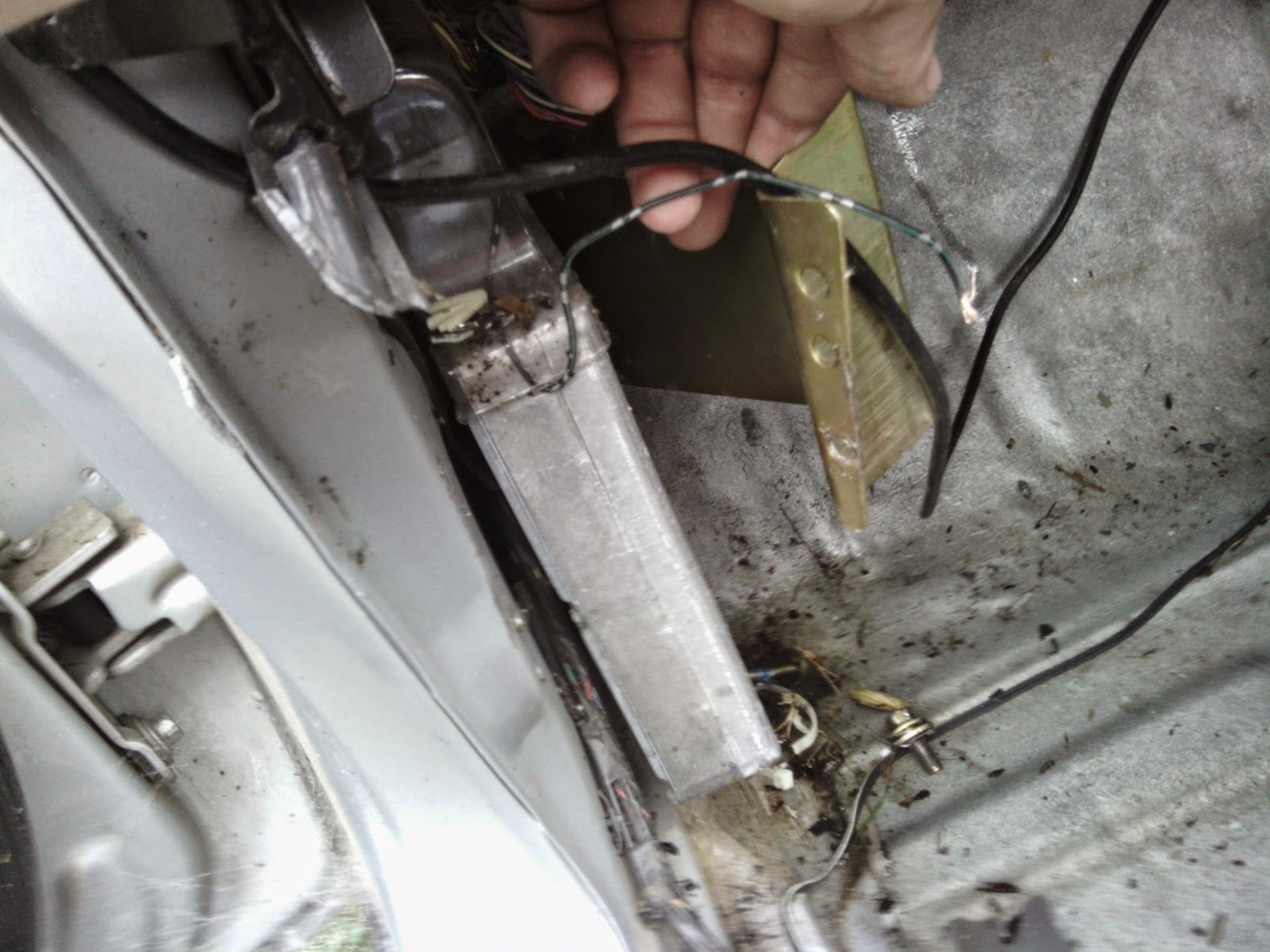
Here Julian is trying to cut out a piece of the trim around the second window so we can get to the edge of it. In the background you can see the damage I managed to do getting the ECU out. That was the other thing that needed to get done while we were out there. So I can easily swap between the stock and custom ECU I am hoping to gut the original enclosure and use the original socket. To get the ECU out of these Falcons first you need to remove a rivet that holds the enclosure down. I didn't have a drill so I used the grinder I got for Christmas.
In my case there was also an earthing wire attached to the rivet that didn't really get much in the way of getting it out. Once the rivet is out then the enclosure will just lift off with a little jiggling and rotating.
With the enclosure out of the way the ECU just lifts out of the way allowing me to remove it from the car. Either through the week or possibly on the weekend I will start tearing down the ECU to see if I can re-use the enclosure and/or the plug and socket. For now here are some pictures showing more details of the ECU and it's plug/socket.


Cheers,
Rex

Wednesday, 3 September 2014

X Axis Progress

Last night I finally got a chance to finish soldering up the X axis motor leads. I had to cut the original soldering I'd done as 3 of the 4 leads were wrong (Not quite sure how that happened) I confirmed what the connections should be, then tested with jumper leads in case I got one pair backwards.

It all worked first time so I soldered it up. 


It's not pretty but it works and for now I just need it to work so I can finish this. I tested again(Learnt my lesson... for now) and taped it up. 

As you can see I have cheated a little and am just using sellotape. I know it's not really intended for this use but the electrical tape I have is rubbish and doesn't even stick to itself, let alone the wire.

Next will be the Z Axis, hopefully soon.

Cheers,
Rex

Friday, 6 September 2013

DC Spindle motors... Woo

I finally tidied up my electronics desk so I could see how I would need to drive the original spindle motors.

Short version:

They are DC motors that seem to be able to go fairly fast at 30V.

Long version:

This is the assembly for the mill option on the converted lathe I had to throw away.
On the top you can see the the speed controller with a switch and a pot to vary the speed.
This is the bit I really wanted to look at as it would be the part to simulate.

After I got a few screws undone it came apart fairly easily.

From there it was a fairly simple process to unscrew the ground cable and take the plastic backing off. From there I could see the conductor side of the PCB.
From there looking at the board it looked like there was a diode either as a reverse polarity protection or as a half wave rectifier. Working on the theory of it being a half wave setup I decided to hook it up to my power supply and see if it would turn or at least produce some kind of cogging effect. When I connected it up and slowly ramped up the supply voltage/current I was rewarded with rotation. Upon experimentation I found it to start spinning with about 0.55A and to just keep turning over at 0.50A.
It's not very obvious but the motor is spinning slowly in this photo. I ramped the voltage all the way up to the maximum that the power supply will provide at about 29.7V which rewarded me with a nice whooshing noise from the air getting blown out of the motor. It looked like it was going pretty fast so I was glad there was a limit to stop me from going any further without having to bolt the thing down. Now I just need to confirm the voltage/current capacity of the PWM supply of the BeBoPr so I know if I need to build a buffer amplifier. The buffer should be able to be a fairly simple design with just a power transistor (probably some kind of FET) attached to a relatively small heatsink.

Being able to easily use these motors and spindles means that I can shave a fair bit of the potential cost of this project and I can focus on more important things like how to get the rotational speed of the spindle when it uses a plastic belt and a DC motor to drive it. I'm thinking some kind of back EMF based system. However the lighting conditions probably won't change too much so some kind of light based system could also be used. This is particularly true of the lathe which has all of the mechanism inside the headstock and is fairly well sealed to light.

Cheers,
Rex