Showing posts with label Mods. Show all posts

Sunday, 7 February 2016

Another project on the go

So after watching this Youtube video. My brother and I have decided to build him a computer based on the same principals as in the linked video. That is using slightly outdated top end or server hardware to build a computer on the cheap.

In this case the goal is to be able to run N3V Games' Trainz: A New Era with reasonable performance. The parts we have selected will allow us to meet the recommended specs for what could be the first time of any of this franchise.

We have only just begun procuring parts for this. But I am very excited about it and I am looking forward to assembling a computer that is more than just the best of the parts I have lying around the place. To find a list of the parts we're using follow this link to see the e-bay collection for the parts we have selected.

We have to wait for the parts to arrive however and there are still some descisions that can't be made until the parts arrive like PSU, case. But stay tuned because this build will enjoy exciting performance for an equally exciting price.

If you have any suggestions or questions please comment below with them so we can all benifit from the discussion.

Cheers,
Rex

Wednesday, 15 April 2015

Work on the next project commencing

Over the weekend I got to start some work on the next project I'm starting. This is the car one. The plan is to turbocharge my mate's 2001 Ford Falcon AU II 4.0L inline 6. The first step in this process is going to be replacing the stock ECU with a custom DIY one, most likely rusEfi. So we went out to my "donor" car that I rolled a few years ago.
It isn't in particularly good shape, but before water got in it too badly it would run. However now the excellent smartshield immobiliser system is working (BEM and ECU or Key Barrel aren't talking I think) and won't let us even turn it over. We headed out to this in an attempt to get the diff out so we can weld it up and make it "Locked" rather than an "Open" diff. That didn't work because we realised that to get the centre of the diff out we would need to remove the entire back axle assembly.


As you can see the outside of the diff was fairly dirty and the muck made it a little difficult to get the cover off. An interesting point to note is the cover had some rust in it, possibly from sitting for too long in a paddock?

Deciding that would be too much work we put the cover back onto the diff and went to work on removing other more interesting things. Julian began removing the remaining few intact windows. He had a process of putting a piece of small wire (from an old tire actually this time) in behind the glass from the outside and working it backwards and forwards until it heated up enough to cut through the caulking holding the glass in place. An easier way to do it is with jumper leads to a car battery so the wire is heated by electrical current rather than friction. However as we don't car about the condition of the body of the car and we didn't have any jumper leads with us we just used friction which also damaged a little of the paint.
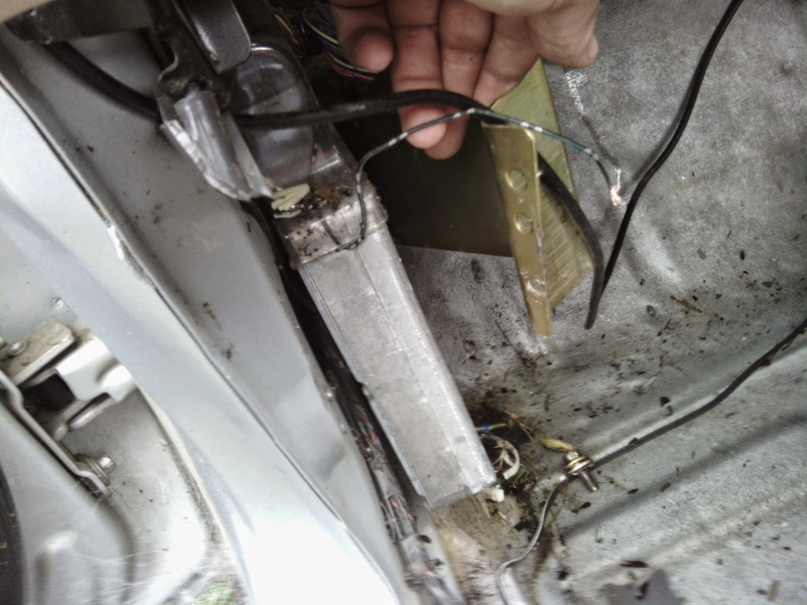
Here Julian is trying to cut out a piece of the trim around the second window so we can get to the edge of it. In the background you can see the damage I managed to do getting the ECU out. That was the other thing that needed to get done while we were out there. So I can easily swap between the stock and custom ECU I am hoping to gut the original enclosure and use the original socket. To get the ECU out of these Falcons first you need to remove a rivet that holds the enclosure down. I didn't have a drill so I used the grinder I got for Christmas.
In my case there was also an earthing wire attached to the rivet that didn't really get much in the way of getting it out. Once the rivet is out then the enclosure will just lift off with a little jiggling and rotating.
With the enclosure out of the way the ECU just lifts out of the way allowing me to remove it from the car. Either through the week or possibly on the weekend I will start tearing down the ECU to see if I can re-use the enclosure and/or the plug and socket. For now here are some pictures showing more details of the ECU and it's plug/socket.


Cheers,
Rex

Thursday, 2 April 2015

On with it's head, then off again. And a return to normal viewing

So I haven't posted for a while, mostly because I have started to use a camera and have since lost all of the photos.

So the long and the short of it is, that I got the head back on, the engine running and everything good; even booked in for rego. Then the welch plug in the back of the head that I hadn't seen while it was off began to leak. Badly. Eventually I managed to not get it out with everything in place so I ended up taking everything off again including the head. With the head off it took all of around 10 minutes to remove and then install a new welch plug. With everything back on I got it started, no leaks. Phew.

From there I got it registered, drove it for a few weeks, took it to Sydney. Took the old oil that I'd put into it out and replaced it with fresh stuff. and gave it a good clean inside, still needs one outside though.

After Driving it for a while I noticed a strange noise from the front end while in 4wd mode. Solution 1, change the oil in the front diff and check what it loos like inside. No dice. Next, start researching online. One option seemed to be that it was "Angry Sparrows" or a squeak from something potentially worn in the front drive shaft. So off with that. It turned out to be a piece of cake, just 8 bolts to remove. Upon inspection I discovered the the apparent reason for the noise was a lack of grease in the ball in the middle of the double carden (CV) joint near the transfer case.

After pulling the double carden apart and damaging(?) one of the universal joints grease was worked into the ball because a replacement kit was around $100 which is somewhat more than I was willing to spend. Everything got re-assembled and then a short drive was taken. Silence, no more angry birds for me.

With that fixed I started to think about the trip I am leaving on tonight and the fact I will be towing a trailer ~1000km each way in an automatic of less than ideal status. I looked into a transmission oil cooler and discovered that there was already one installed. I also wanted to be able to measure the oil temperature so I installed a SAAS oil temp. gauge as a transmission temperature gauge. The install was very straight forward and didn't take too long except for the cutting of the hard line. That had to be done by hand with a hacksaw blade as we had nothing else that would fit in the small space.

So from here I have a 3 new projects all of which are exciting and I am looking forward to all of them. One involves a road trip this weekend, one involves rainwater and the last involves my wreck, EFI, turbos and someone else's car. All will be exciting and lots of learning will be done in all 3 new projects.

Until next time, Cheers.
Rex

Thursday, 29 November 2012

Laptop Oscilloscope original state

Here are the photos as promised yesterday. I apologise for the quality but my iPod 4G was pretty much the only camera that functions reasonably well and reliably.


 The basic overview. The tag in the back right corner is a repair tag from when grandpa got it fixed at some stage.

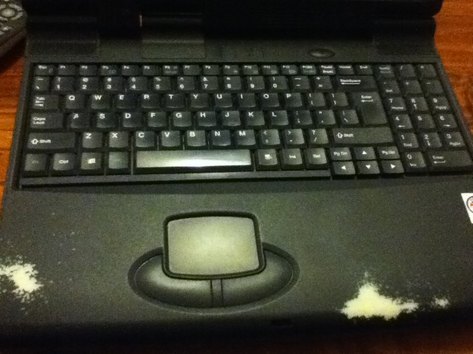
 A view of the screen, keyboard and mousepad. the screen and keyboard should be re-usable but I'll need to find a new mousepad and buttons.


Some views of the bottom. At bottom with all of the removable sections partly removed. Clockwise from top right there is the CDROM drive, HDD bay, Floppy/Zip drive bay.

Here all of the removable modules are removed. Bottom left we can see the modem module with broken ribbon cable from a previous teardown I did.
 Here is the backplate with (L to R) VGA out, RS-232, 2xUSB, proprietry breakout plug, RCA video out, S-Video out, Printer port.

 2.5" HDD bay.
 CDROM sitting on top of HDD bay to get some angle on the front.
 Zip and Floppy drives side by side on top of HDD on top of CDROM, once again for some angle.
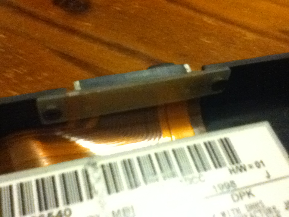
 A close up of the connector. Should be pretty easy for me to put in my own connectors.
 The where the battery was. It's a pretty big hole and a raspberry pi would probably fit in this space alone. Maybe some other pluggable module... Perhaps a replaceable CPU/RAM module or something.
The battery in all it's brick-like glory. It doesn't work as a battery anymore but if I did want to I could probably re-pack the original cells... Perhaps even increasing the capacity. :)

If you want any more detailed pictures or info post a comment and I'll get some for you.

Wednesday, 28 November 2012

Nerf Stampeed electronics upgrade

This is a post I was going to make a little while ago about a fairly basic project to get me into Amtel's AVR microcontrollers... I had some problems with the internet on that day and have only just rediscoverd the draft that was saved :)


So I'm not happy with the stock electronics for the Nerf Stampeed. Using a 7 shot clip you can easily fire away all of your darts and still not hit anything. Also the 6 D cell batteries are a pain to replace and are massively heavy.

The solution:

Put a small microcontroller such as an Amtel AtTiny of some description, replace the current power switch with a 3-way switch to allow selecting between:
-Full Auto(Stock Setting)
-Burst(fires 2 or 3 darts at a time)
-Semi-Auto(fires 1 shot but automatically re-cocks)

Some way of displaying the number of rounds fired in battle and the battery level should be easy to set up. If I can find a way to differentiate between different magazines then a readout showing how many are left in the mag. would also be useful.

A display like this only needs an SPI interface, everything else can be controlled with digital I/O except for reading the battery state, the best solution for which I don't quite know right now but will probably need an ADC channel.

This is a fairly quick flowchart I did up showing the basic functions that will be called and when... not quite up to drawing a flowchart to show exactly how each function works... but I figure this is a start.

If you want to know why I did up a flowchart for this just ask me to put up the Qt code and flowchart that I taught myself and wrote in 1 week or so... the flowchart was about 2.5m high when printed so small it was barely readable... Originally I was trying to work it all out in my head... doesn't work that way... not like the simple little things they wanted me to do flowcharts for in my sfotware design and development course...

Finally... New project :)

Finally I've decided what to make my next new project. A DSO... This oscilloscope will be housed in the case of an old laptop that was given to me a while ago by my grandfather after they got a much better one. From memory it's current specs are in the vicinity of: 400-500 MHz processor(Pentium?), 64MB RAM, 4GB 2.5" IDE HDD, broken mousepad, decent screen (will run up to 1024x786?), came with win98, struggles to run cron, X11 and a window manager(twm?) on top of a CLI Ubuntu install.

All this will be replaced allowing me to start from scratch... I will probably keep the keyboard and screen, even if I have to set up an AtTiny or similar to get the interfaces in a format I want. At this stage looking at using an ARM processor or SoC. The CDROM bay will be replaced with pluggable modules with a digital interface to the main board allowing me to change and upgrade input channels or make a computer controlled function generator/DSO that can be controlled from any computer (Running Linux of course :) ). At this stage to allow remote control ethernet/WIFI is planned with an interface probably built from Qt. As well as being remote controllable the oscilloscope will be locally controllable, with the bootloading being handled by coreboot with a linux kernel payload.

I want to be able to use this to help me debug amateur radio rigs up to the 40m band to start with. The pluggable ADC modules allow me to improve if I need better frequency/accuracy. Basic features will include:
-Local control to allow full functionality as a normal DSO.
-Updatable firmware so new features can be implemented.
-Miniumum 50MHz bandwidth for initial product(excluding prototypes).
-Network connectivity to allow remote monitoring.
-Possibly battery, to allow monitoring in locations with limited power outlets
-Using only free and open source tools to design and sharing the designs as open source(github?)

Hopefully soon I'll get a picture of the laptop in it's current condition so you can get an idea of how much space internally I have to work with :)