I'm back at a point where I can start buying more parts to get the Land Rover back on the road.
You may have noticed that there are some lights missing from it. Namely the indicators, park & brake lights.
If you hadn't, this picture shows where 2 of them go nicely.
I have ordered a set of replacements from Rover Parts which will look like this:
Image from http://www.roverparts.com.au/
They are not quite exactly identical to the original parts. However they have just come off a later model. They will still fit in the same space and get wired up the same.
I have tested some of the wiring that is still in the back. The wire for one of the indicators is still good and works, but I'll need a helper to test the brake lights. Also I'm hoping a little more load from more lights will mean that the indicator flasher can has enough current going through it to cause the lights to actually flash.
While I've got the front of the engine bay apart for replacing the water pump here I have the battery sitting on my back veranda not doing much. So I figured I would give it a charge. However I don't have a proper battery charger. I do have a more sophisticated tool that will charge a battery though.
Enter the laboratory power supply. This one is a fairly cheap one that I picked up off ebay a couple of years ago. It's noting to write home about but it is more than enough for this job. The reason it will work for this is that I can set it to output a maximum of 13.8V which is the standard charging voltage for lead acid batteries. It also has a constant current mode which would be useful for smaller batteries which should be charged slower, but a big one like this can probably handle as much as this relatively small supply will provide.
I just used a set of jumper leads to connect the battery as they are all that I have that will fit the posts built into the battery.
Here we are after about 1/2 to 3/4 of an hour. The battery is still accepting .52A of current into it at the full charging voltage of 13.8V which means that it is essentially full. Certainly close enough for me. Tomorrow or the day after I am going to pull the 2nd battery out of the Land Rover and see if it will charge up. The previous owner said that it didn't charge for him but I want to see exactly what happens as sometimes a "dead" lead acid battery can be brought back to life.
I will leave this battery on charge until I go to bed tonight to trickle it up as much as it will, then I will take it off the charge to reduce the risk of something going wrong, boiling, hydrogen production, etc.
On the weekend I spent some time volunteering at our local miniature railway club. One of the things I have worked on is the signalling system. It has been built and patched over the years and didn't have any kind of diagram in place. So before anything broke we figured it would be best to build a diagram so that when something does break down we have something to look at.
Where the power starts. 12V DC goes down that PVC pipe into the ground and appears somewhere outside, then feeds the signals.
Here we have one set of points, under one of the plates is a pneumatic motor and a switch that triggers the signals at the station.
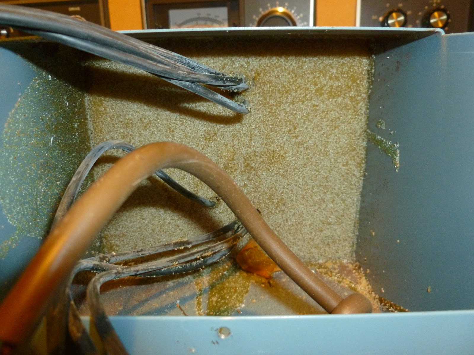
Hmmm, I don't remember ever reading about using leaves as insulation. Perhaps we need to start cleaning this out more often.
This is where all the magic happens. The circuit under here is what ensures that all of the signals light when they should.
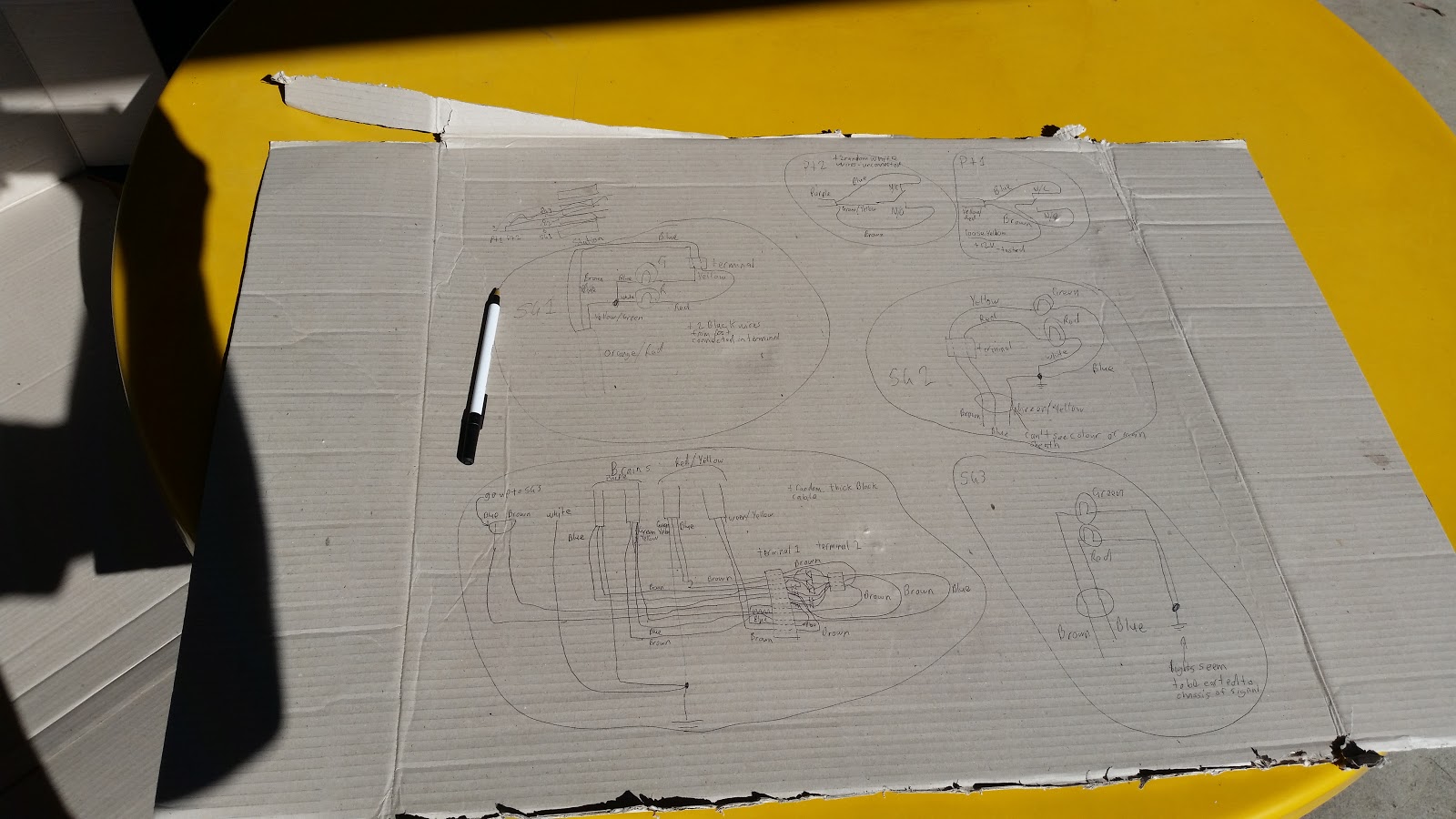
It looks a little less of a rats nest now that it's been pulled out of the box but still pretty confusing to begin with. The trick here is to pick a point to start from, draw a rough sketch that is only for your notes and re-draw later if you need to make anything neater. Being Methodical will help a lot here.
A little offputting, This is the door of the box and bside it is a piece of scale that came off the inside. It certainly pays to clean things up a little before trying to make sense of things. Trying to work out what wire went where would have been much more difficult. It certainly pays to spend a little more time making sure everything is in order before doing what you are in there for.
Notes mk1. These were only done for me, jotted down roughly for me to translate into something that can be understood later.
And here's the super duper accurate neat and legible drawing. No it may not look like much, but you don't need something that has been drawn by engineers with a dozen letters after their names on multi-thousand dollar computers. All that is needed is some time and care to the job being done and anyone can learn to do this sort of thing.
Remember, just because you don't have a piece of paper saying you can do something, doesn't mean that you can't do them. Conversely, having that paper doesn't mean you can do something better than anyone else.
One of my relatives who recently got a computer upgrade had the old Hard Drive from the old machine and was concerned that there could be some sensitive data on it still. So, being the helpful young man I am I volunteered to destroy any data that might be hiding in there still.
This is where we start, It's an older IDE drive that I could probably use in one of my machines, but I have given in to the SATA cables and now I have a very hard time justifying why I should be keeping a drive that needs a ribbon cable, so I won't.
These are what hold the top on. These are just a normal Torx T8 screw. If you buy a small toolkit from Jaycar or many other electronics hobby stores you will probably find it includes some of these.
There's a sneaky one here hiding under the label. Make sure you unscrew it because otherwise no matter how hard you try, that top isn't coming off.
Once all the screws are out just prise around the edges with a screwdriver or another fairly thin tool.
The top should come off fairly easily after that, if not look for more screws under the label. (Ask me how I know.) If you look closely you can see there is a bead of some kind of semi flexible sealant around the edge of the lid. This is to keep air and more importantly dust out. These drives are assembled in a cleanroom type environment as any particles can significantly reduce the life and reliability of these.
Some drives do have a vent in them. Those that do always have some kind of filter over the vent to keep contamination out of the drive. The vent is required as during operation the internals of the drive change temperature. This causes the air inside to expand and it needs somewhere to go, otherwise it may damage the case.
Here we can see the interesting parts of the drive. The big silver disk is the platter where the data is actually stored. The metal arm that is pointing to near the center of the platter is the read/write head. The very end of it floats on an air bearing when the drive comes up to speed. If the air bearing fails for whatever reason the head can crash into the platter which can cause scratches and other damage.
This is a short video I put together of me destroying this Hard Disk. Don't watch if you have strong Hard Drive sympathies.
For anyone who doesn't want to load the video this is what the top of the platter looked like after machining it with a screwdriver bit.
I don't think anything is going to be recovered from this drive. But to be sure I'm going to be keeping a magnet on top of it and moving it occasionally, just to be sure.
If there's anything else you want to see inside and/or tortured like this drop a not in the comments and we'll see what I can do.
Sometimes we come across projects or sub projects that we don't want to take on because we are worried what others might think, if it's safe, if others will think it's safe, if it's too expensive. The problem is that when we let these fears and concerns govern what we allow ourselves to do then we end up not accomplishing anything near what we are capable of.
This is something that I have struggled with on various projects over the years, is it safe? What will others think of me doing it? Whatever the case may be. On the instances when I have put these fears into their place by stopping and working out just what the impact will be, then after putting into place safety controls I have always found these projects to be worthwhile. This one today is one of them. Here was my problem:
The controller for the CNC Lathe runs on 110V not the 240V that comes from the walls here. When I got the machines I had a few cords that would connect them to a transformer box so they could be used with a 240V wall supply. Unfortunately I have lost said cables and to be able to run the Lathe I need to get 110V to it. Bugger.
This is where fear came into it. From the time I have started playing with electronics there has always been an unspoken rule that you just don't have anything to do with line voltage as a hobbyist. This is a very safe rule. However in this situation it would've stopped me from being able to run the lathe again unless I found the power cord (Unlikely). So after taking stock of the risks (electrocution) and working out controls (unplug and leave for a while to let any charge dissipate, test to make sure nothing is shorted to the case before re-connecting) I realized that this could be fixed safely.
And here's the finished product. I can now use a normal power cord like I would use for a computer to power the lathe with 110V.
That's where the scaryness happens. The transformer is potted in epoxy so that's all quite solid.
Looks like I'm not the only one who chain drills and doesn't fully clean up the edges. I had to take off some of the peaks before the new socket would go on.
Testing all of the connections. I'm using an old analog multimeter on ohm reading to check for shorts. It does still work, certainly well enough to show a short circuit.
That's all for today, the next post will be my 100th post on this blog so I am working on something cool for that so stay tuned.
And remember, don't let your fears tell you that something can't be done. There's always a safe way.
The mill is running again, in it's new spot inside the house so I should be able to get to work on it a bit more often. This is where it is now, on the new desk with my laptop beside it running the controls
I had the lab power supply out to see if I could run the spindle off it. However even with the knob for current all the way up it was still getting limited so I think that's going to be a no-go. The good news is that I can still run it from the accessories port on the Lathe control box because I haven't gutted it yet.
It's a little bit dirty but not too bad and with the shield shut then there shouldn't be any issues with bits getting into the rest of the room which is good considering this is above my servers.
Here's the interface I am using for now. I'm hoping to get Machineface/Cetus/mkwrapper working so I can use any computer to control this, but for now I'm connecting with a VNC connection because mkwrapper doesn't seem to like being run in such a way as it can be accessed from outside that computer.
Finally, here is a short video I took while I was making sure everything still worked. I still need to set the maximum speed and tune the acceleration for each of the axies but I will get to that eventually. You can hear that when it's set right it's nice and smooth. But otherwise it sounds like somethings grinding.
Just a quick update on how the mill is going as that's the only thing that's actually had anything done on it recently. I finally got the software issues sorted and worked out a display, then when I pressed the go button to power on the motors they hissed like they should for a fraction of a second. Then.. all of the power died to the board.
A second test confirmed that this is consistent behavior unfortunately. I think what is happening is that the turn on current draw of the steppers is too high for the computer PSU and it trips the overload protection. To test this what I'm going to do is connect my bench power supply in parallel with the computer supply and then after starting the motors wind down the current. That should tell me if the computer PSU will handle the base load current.
If it will then I will probably put some kind of large capacitor across the 12V rail and GND to help minimize the surge. I may do a quick writeup on the display arrangement I finally got working, particularly if there is some interest there.
All week I've been trying to work out what this is supposed to do all week. It came from the base of the my vertical HF Antenna. It's some kind of inductor that has one end connected to the shield and the other end connected to the actual antenna. The centre of the coax is connected to the same point on the antenna through the middle of the inductor. To see me dis-assemble the antenna or if you have any suggestions keep reading past the break.
I've finally got more work done on the Mill. I was hoping to get a shot of the control box powered up with the laptop running the control software next to it for the cover photo. However it seems that I need to keep playing with the software a little longer.
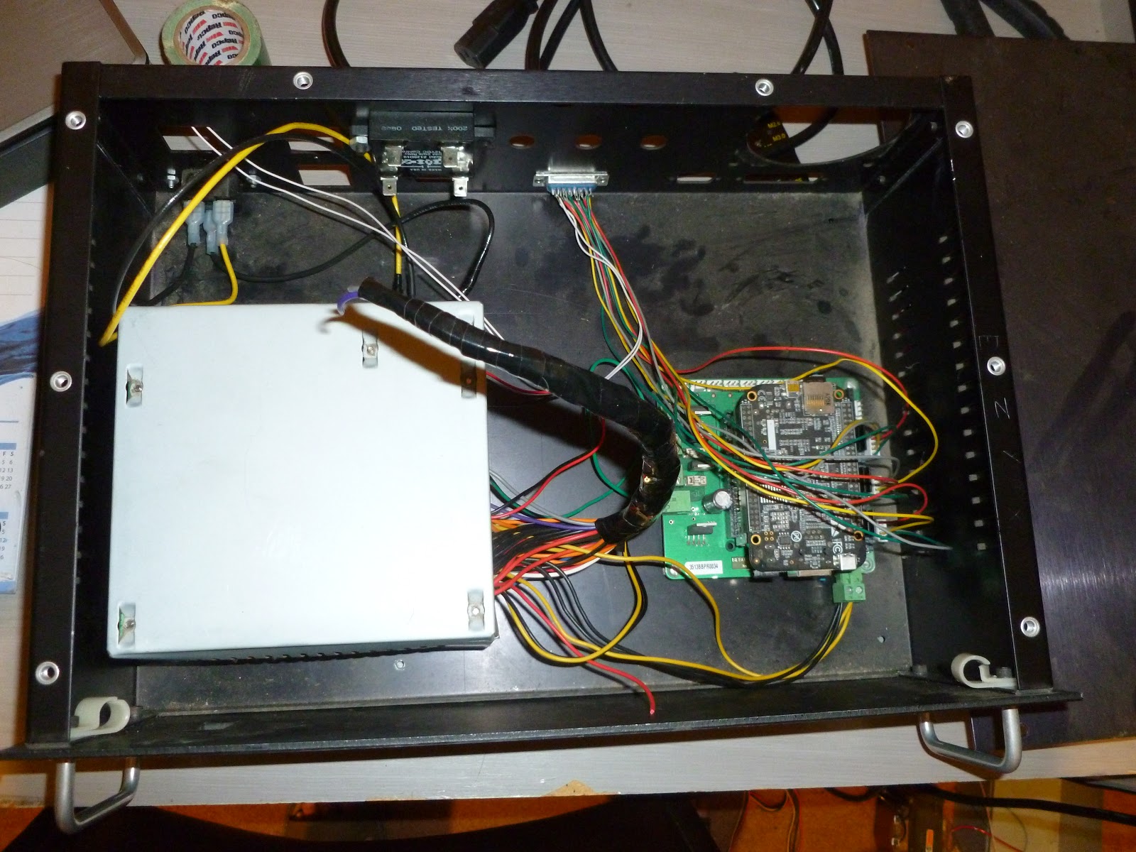
Instead you get a photo of the finished product as it stands. I know the wiring isn't the neatest or prettiest. But you can take my word for it that it does work now. Follow on after the break to see how I got to this point.
So I managed to get a little done over the weekend. The grounding for my HF radio has always been a little unsatisfactory to me. So I set out to improve that a little. Currently I only have a stake half buried into the ground below my vertical antenna.
To improve this I have added 4 radials of equal length at as long as possible within my yard. I know that 4 radials is not ideal, however I am expecting a significant improvement over the current system. One of the biggest concerns I have is with my connection point.
This is where the joint between the radials and the wire that will connect to the bracket for the antenna. Unfortunately at this point I tried to heat up my soldering iron and it just won't heat up. So I'm going to have to see if I can borrow a soldering iron from somebody.
So seeing as I couldn't do anymore out here I decided to put my VHF Ham set into the Jeep. This was one of those projects that I got a little excited about so I don't have any photos of that. But I still have to mount an antenna so I'll get some pictures then.
After I finished setting up the radio I decided to chase some wires that are attached to what seem to be microphones in the cab. Chasing those lead me to this little box:
Chasing the wires from the other end of that box lead through the firewall and eventually to this box under the bonnet on the passenger's side:
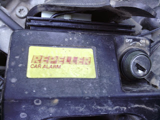
Upon unplugging this and removing it from the car I was quite surprised by what I found on the opposite side of that box.
So this was not really expected and thankfully off and not activated, otherwise we could very well have had a very exciting time getting to this stage. I have it off and on my desk at the moment so I'll see if there is anything useful or interesting and I might put it back in. Otherwise I will see if I can remove all of the wiring that it has, just to minimize the spaghetti mess inside the car.
I spent most of the day working on the Class D Amp. I got a roughly sawtooth oscillator based around a 555 timer going after I sorted out some problems with power supply filtering. I then added in a buffer amp stage to make sure I wasn't going to be loading up the oscillator, after going through the buffer the waveform was a little mangled but I pressed on.
I then tried to put a PWM stage with the output from my iPod and the buffer stage. In the process of doing that I managed to knock some critical wires loose and spent the next few hours trying to work out what had changed to stop it working. During this process I realized that even with all of the capacitors in my collection in use there was still ripple on the power rails in time with the bottom of the sawtooth. The other thing I realized that to get the PWM working with Audio frequencies I'm going to need to up the frequency.
To solve the first problem I'm going to go into Jaycar tomorrow and pick up some LM7905's if they have them and possibly some generic BJT's in case I need to make a constant current supply for the Sawtooth oscillator.
To solve the second problem I have just substituted a smaller capacitor in the oscillator. This has definetly increased the frequency by an order of magnitude; so hopefully that problem has been solved.
If anyone wants some diagrams or pictures of my setup let me know in the comments and I'll put some up.
I finally tidied up my electronics desk so I could see how I would need to drive the original spindle motors.
Short version:
They are DC motors that seem to be able to go fairly fast at 30V.
Long version:
This is the assembly for the mill option on the converted lathe I had to throw away.
On the top you can see the the speed controller with a switch and a pot to vary the speed.
This is the bit I really wanted to look at as it would be the part to simulate.
After I got a few screws undone it came apart fairly easily.
From there it was a fairly simple process to unscrew the ground cable and take the plastic backing off. From there I could see the conductor side of the PCB.
From there looking at the board it looked like there was a diode either as a reverse polarity protection or as a half wave rectifier. Working on the theory of it being a half wave setup I decided to hook it up to my power supply and see if it would turn or at least produce some kind of cogging effect. When I connected it up and slowly ramped up the supply voltage/current I was rewarded with rotation. Upon experimentation I found it to start spinning with about 0.55A and to just keep turning over at 0.50A.
It's not very obvious but the motor is spinning slowly in this photo. I ramped the voltage all the way up to the maximum that the power supply will provide at about 29.7V which rewarded me with a nice whooshing noise from the air getting blown out of the motor. It looked like it was going pretty fast so I was glad there was a limit to stop me from going any further without having to bolt the thing down. Now I just need to confirm the voltage/current capacity of the PWM supply of the BeBoPr so I know if I need to build a buffer amplifier. The buffer should be able to be a fairly simple design with just a power transistor (probably some kind of FET) attached to a relatively small heatsink.
Being able to easily use these motors and spindles means that I can shave a fair bit of the potential cost of this project and I can focus on more important things like how to get the rotational speed of the spindle when it uses a plastic belt and a DC motor to drive it. I'm thinking some kind of back EMF based system. However the lighting conditions probably won't change too much so some kind of light based system could also be used. This is particularly true of the lathe which has all of the mechanism inside the headstock and is fairly well sealed to light.
I have just ordered a new lab power supply from ebay. It should be arriving between next tuesday and the tuesday after. So Look forward to some work with op-amps after that.
Last night I finally got some time to get some prototyping done. I figured that I should start with a regulator circuit so that I have smooth power for using with op-amps. I will build a more efficient and permanent supply when I need it a bit more but using what was on hand I have a half reasonable output from this hobby train controller that was sitting in the garage.
Just about to start work on the triangle wave generator from this page.
Stay tuned.
Cheers,
Rex
EDIT: Just finished compiling LFS on my server so I should have more time to work on this.
Here's a little block digram I did up to help me work out the best way to connect the ADC(s), RAM and CPU. If anyone out there has any suggestions please leave a comment.
So today while doing the thoroughly mentally stimulating task of watering trees at work all day I had an epiphany. I am building a Digital Storage Oscilloscope ie. I can have 2 programs that run and have them mutually exclusive. A capture program that reads the state of the ADC(s) and pushes them to a more stable memory location(seperate section of RAM, Main HDD[my be a section of flash memory on board] or Dedicated section of Flash memory). The pseudo-code for this would be along the lines of: Reset counter
While Stop = False do
Move state_of_ADC to register0
Move register0 to Permanent_Location[counter]
counter = counter +1
EndWhile
This would give a sampling rate that can be calculated fairly easily. The instructions are fairly basic so they should each only take 1 cycle to execute. Therefore 5 cycles are required to monitor the state. Therefore we just divide the clockspeed of the CPU by 5 to give us the sampling frequency(assuming CPU at 1GHz):
1GHz/5=200MHz
That's a 200MHz sampling rate. The only problem with this method is that the only real way to change the sample rate is to change the CPU's clock speed... But if I'm going to build a radio from scratch then I dare say I'll get used to adjusting frequencies with a voltage...
The other program would be a GUI that allows the "settings" to be adjusted and a graph to be displayed. The "settings" would only effect the display. Unless I decide to implement software controllable attenuation or something useful like that. The attenuation would be done before the ADC and would be instructed to attenuate through the communication bus from the ADC which is activated for reverse transmission by sending a pin to say -5V which shouldn't happen in any other situation.
Anyway is anyone finds this helpful/instructive/wrong don't hesitate to leave a comment, more comments inspires me to write more :)
p.s. If anyone sees the HTML tags wrong or wants me to go through the tags I used here let me know any I'll put something up.
I just wired up a test harness to see what voltage the smoke machine would cut off current to the heating coil when I stopped(pretty unusual) and thought(don't know where this came from...) I should probably test it without anything connected to the PCB just to see what happens. So I did and lo and behold, it thought it was up to temperature... Check the voltage accross the pins... 2.5-3V there... Resistance of the temperature probe? 3 ohms... Hmmm... might not be a thermocouple... time for some more tests...
Attach the probe to PCB... heater turns on... remove it heater turns off... I can hear the relay ticking so that's not what caused it to overheat... some more research needed methinks... Wikipedia here I come...
Rather than just getting a high resistance to drop the voltage I realized that a higher current would also. By putting a resistor in parallel with the potentiometer I can increase the current flowing through the first resistor and use a smaller, more available resistor there to drop the same voltage.
This is the schematic I did up in KTechLab to test my theory. the 1M resistor represents the smoke machine input. the max. voltage possible with this arrangement is about 30mV(50mV with a 5V supply). This means I should be able to supply the required 25mV for my max. temperature.
Looking at the Wikipedia page on thermocouples I found this table:
Type
Temperature range °C (continuous)
Temperature range °C (short term)
Tolerance class one (°C)
Tolerance class two (°C)
IEC Color code
BS Color code
ANSI Color code
K
0 to +1100
−180 to +1300
±1.5 between −40 °C and 375 °C ±0.004×T between 375 °C and 1000 °C
±2.5 between −40 °C and 333 °C ±0.0075×T between 333 °C and 1200 °C
J
0 to +750
−180 to +800
±1.5 between −40 °C and 375 °C ±0.004×T between 375 °C and 750 °C
±2.5 between −40 °C and 333 °C ±0.0075×T between 333 °C and 750 °C
N
0 to +1100
−270 to +1300
±1.5 between −40 °C and 375 °C ±0.004×T between 375 °C and 1000 °C
±2.5 between −40 °C and 333 °C ±0.0075×T between 333 °C and 1200 °C
R
0 to +1600
−50 to +1700
±1.0 between 0 °C and 1100 °C ±[1 + 0.003×(T − 1100)] between 1100 °C and 1600 °C
±1.5 between 0 °C and 600 °C ±0.0025×T between 600 °C and 1600 °C
Not defined.
S
0 to 1600
−50 to +1750
±1.0 between 0 °C and 1100 °C ±[1 + 0.003×(T − 1100)] between 1100 °C and 1600 °C
±1.5 between 0 °C and 600 °C ±0.0025×T between 600 °C and 1600 °C
Not defined.
B
+200 to +1700
0 to +1820
Not Available
±0.0025×T between 600 °C and 1700 °C
No standard use copper wire
No standard use copper wire
Not defined.
T
−185 to +300
−250 to +400
±0.5 between −40 °C and 125 °C ±0.004×T between 125 °C and 350 °C
±1.0 between −40 °C and 133 °C ±0.0075×T between 133 °C and 350 °C
E
0 to +800
−40 to +900
±1.5 between −40 °C and 375 °C ±0.004×T between 375 °C and 800 °C
±2.5 between −40 °C and 333 °C ±0.0075×T between 333 °C and 900 °C
Chromel/AuFe
−272 to +300
n/a
Reproducibility 0.2% of the voltage; each sensor needs individual calibration.
I also had a closer look at the sheaths that the wires for the thermocouple are insulated with. The one going to the +ve port had red lines and the one to the -ve port had what appeared to be black lines in it. The background colour is white.
Based on that table then and if we assume the black is actually a very dark blue then the thermocouple used is most likely going to have been a K type which appear to be fairly popular so it should be easy to find a new one.
With 41 µV/°C I can calculate the maximum voltage I'll need to be able to spoof the thermocouple up to 600°C. I picked this as it shouldn't even go close but in case it does I can still test it.
With 3.3V avaliable from an old ATX PSU and (with some help from here) a voltage of 25.703mV(measuring 600°C reference 20°C) accross the thermocouple:
Voltage drop across fog machine=0.025703V
Voltage drop across resistors=3.274297V
Current flow from fog machine=V/R
=0.025703/1000 000
=0.000000026A
Resistance required=V/I
=3.274297/0.000000026
=125934500Ω
=125934.500kΩ
=125.934500MΩ
Which is pretty close to 126MΩ
However when I run this through KTechLab (Better than a SPICE simulator for a quick calculation) 10MΩ seems to be enough... perhaps I neglected to calculate current flow through the resistance array? I'll re-post once I have more info...