
Sunday 23 December 2012
DSO Block Digram
Wednesday 19 December 2012
DSO Revelations
So today while doing the thoroughly mentally stimulating task of watering trees at work all day I had an epiphany. I am building a Digital Storage Oscilloscope ie. I can have 2 programs that run and have them mutually exclusive. A capture program that reads the state of the ADC(s) and pushes them to a more stable memory location(seperate section of RAM, Main HDD[my be a section of flash memory on board] or Dedicated section of Flash memory). The pseudo-code for this would be along the lines of:
This would give a sampling rate that can be calculated fairly easily. The instructions are fairly basic so they should each only take 1 cycle to execute. Therefore 5 cycles are required to monitor the state. Therefore we just divide the clockspeed of the CPU by 5 to give us the sampling frequency(assuming CPU at 1GHz):
The other program would be a GUI that allows the "settings" to be adjusted and a graph to be displayed. The "settings" would only effect the display. Unless I decide to implement software controllable attenuation or something useful like that. The attenuation would be done before the ADC and would be instructed to attenuate through the communication bus from the ADC which is activated for reverse transmission by sending a pin to say -5V which shouldn't happen in any other situation.
Anyway is anyone finds this helpful/instructive/wrong don't hesitate to leave a comment, more comments inspires me to write more :)
p.s. If anyone sees the HTML tags wrong or wants me to go through the tags I used here let me know any I'll put something up.
Reset counter

While Stop = False do


 Move state_of_ADC to register0

Move register0 to Permanent_Location[counter]

counter = counter +1

EndWhile
This would give a sampling rate that can be calculated fairly easily. The instructions are fairly basic so they should each only take 1 cycle to execute. Therefore 5 cycles are required to monitor the state. Therefore we just divide the clockspeed of the CPU by 5 to give us the sampling frequency(assuming CPU at 1GHz):
1GHz/5=200MHz
That's a 200MHz sampling rate. The only problem with this method is that the only real way to change the sample rate is to change the CPU's clock speed... But if I'm going to build a radio from scratch then I dare say I'll get used to adjusting frequencies with a voltage...The other program would be a GUI that allows the "settings" to be adjusted and a graph to be displayed. The "settings" would only effect the display. Unless I decide to implement software controllable attenuation or something useful like that. The attenuation would be done before the ADC and would be instructed to attenuate through the communication bus from the ADC which is activated for reverse transmission by sending a pin to say -5V which shouldn't happen in any other situation.
Anyway is anyone finds this helpful/instructive/wrong don't hesitate to leave a comment, more comments inspires me to write more :)
p.s. If anyone sees the HTML tags wrong or wants me to go through the tags I used here let me know any I'll put something up.
Sunday 9 December 2012
Not a thermocouple? :/
I just wired up a test harness to see what voltage the smoke machine would cut off current to the heating coil when I stopped(pretty unusual) and thought(don't know where this came from...) I should probably test it without anything connected to the PCB just to see what happens. So I did and lo and behold, it thought it was up to temperature... Check the voltage accross the pins... 2.5-3V there... Resistance of the temperature probe? 3 ohms... Hmmm... might not be a thermocouple... time for some more tests...
Attach the probe to PCB... heater turns on... remove it heater turns off... I can hear the relay ticking so that's not what caused it to overheat... some more research needed methinks... Wikipedia here I come...
Attach the probe to PCB... heater turns on... remove it heater turns off... I can hear the relay ticking so that's not what caused it to overheat... some more research needed methinks... Wikipedia here I come...
mV Voltage Divider
Rather than just getting a high resistance to drop the voltage I realized that a higher current would also. By putting a resistor in parallel with the potentiometer I can increase the current flowing through the first resistor and use a smaller, more available resistor there to drop the same voltage.
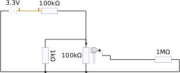
This is the schematic I did up in KTechLab to test my theory. the 1M resistor represents the smoke machine input. the max. voltage possible with this arrangement is about 30mV(50mV with a 5V supply). This means I should be able to supply the required 25mV for my max. temperature.
Saturday 8 December 2012
Thermocouple woes
Looking at the Wikipedia page on thermocouples I found this table:
I also had a closer look at the sheaths that the wires for the thermocouple are insulated with. The one going to the +ve port had red lines and the one to the -ve port had what appeared to be black lines in it. The background colour is white.
Based on that table then and if we assume the black is actually a very dark blue then the thermocouple used is most likely going to have been a K type which appear to be fairly popular so it should be easy to find a new one.
With 41 µV/°C I can calculate the maximum voltage I'll need to be able to spoof the thermocouple up to 600°C. I picked this as it shouldn't even go close but in case it does I can still test it.
| Type | Temperature range °C (continuous) | Temperature range °C (short term) | Tolerance class one (°C) | Tolerance class two (°C) | IEC Color code | BS Color code | ANSI Color code |
|---|---|---|---|---|---|---|---|
| K | 0 to +1100 | −180 to +1300 | ±1.5 between −40 °C and 375 °C ±0.004×T between 375 °C and 1000 °C | ±2.5 between −40 °C and 333 °C ±0.0075×T between 333 °C and 1200 °C | |||
| J | 0 to +750 | −180 to +800 | ±1.5 between −40 °C and 375 °C ±0.004×T between 375 °C and 750 °C | ±2.5 between −40 °C and 333 °C ±0.0075×T between 333 °C and 750 °C | |||
| N | 0 to +1100 | −270 to +1300 | ±1.5 between −40 °C and 375 °C ±0.004×T between 375 °C and 1000 °C | ±2.5 between −40 °C and 333 °C ±0.0075×T between 333 °C and 1200 °C | |||
| R | 0 to +1600 | −50 to +1700 | ±1.0 between 0 °C and 1100 °C ±[1 + 0.003×(T − 1100)] between 1100 °C and 1600 °C | ±1.5 between 0 °C and 600 °C ±0.0025×T between 600 °C and 1600 °C | Not defined. | ||
| S | 0 to 1600 | −50 to +1750 | ±1.0 between 0 °C and 1100 °C ±[1 + 0.003×(T − 1100)] between 1100 °C and 1600 °C | ±1.5 between 0 °C and 600 °C ±0.0025×T between 600 °C and 1600 °C | Not defined. | ||
| B | +200 to +1700 | 0 to +1820 | Not Available | ±0.0025×T between 600 °C and 1700 °C | No standard use copper wire | No standard use copper wire | Not defined. |
| T | −185 to +300 | −250 to +400 | ±0.5 between −40 °C and 125 °C ±0.004×T between 125 °C and 350 °C | ±1.0 between −40 °C and 133 °C ±0.0075×T between 133 °C and 350 °C | |||
| E | 0 to +800 | −40 to +900 | ±1.5 between −40 °C and 375 °C ±0.004×T between 375 °C and 800 °C | ±2.5 between −40 °C and 333 °C ±0.0075×T between 333 °C and 900 °C | |||
| Chromel/AuFe | −272 to +300 | n/a | Reproducibility 0.2% of the voltage; each sensor needs individual calibration. | ||||
Based on that table then and if we assume the black is actually a very dark blue then the thermocouple used is most likely going to have been a K type which appear to be fairly popular so it should be easy to find a new one.
With 41 µV/°C I can calculate the maximum voltage I'll need to be able to spoof the thermocouple up to 600°C. I picked this as it shouldn't even go close but in case it does I can still test it.
With 3.3V avaliable from an old ATX PSU and (with some help from here) a voltage of 25.703mV(measuring 600°C reference 20°C) accross the thermocouple:
Voltage drop across fog machine=0.025703V
Voltage drop across resistors=3.274297V
Current flow from fog machine=V/R
=0.025703/1000 000
=0.000000026A
Resistance required=V/I
=3.274297/0.000000026
=125934500Ω
=125934.500kΩ
=125.934500MΩ
Which is pretty close to 126MΩ
However when I run this through KTechLab (Better than a SPICE simulator for a quick calculation) 10MΩ seems to be enough... perhaps I neglected to calculate current flow through the resistance array? I'll re-post once I have more info...
Sunday 2 December 2012
More progress on the fog machine
To test my hypothesis about the temperature sensor being a thermocouple I realized that a thermocouple would have something like an op-amp as a buffer amp and to get the low voltage up to a logic level. An op-amp has an (ideally) infinite (actually) really high input impedance. This high impedance means that the amp does not load down the input circuit with high current draw.
I=V/R
I=V/infinity
I=0
This is why an op-amp has a high input impedance.
The temperature probe connections have a resistance of around 1000k. That's pretty high, which when coupled with the polarity markings indicates that there is an op-amp on the board and the temperature probe is a low current voltage source. Also known as a thermocouple.
This means I can now simulate the presence of the temperature probe by supplying an appropriate voltage(not sure how big yet though). By simulating the presence of the thermocouple I can test if the electronics will turn off the heater current at some point which means that it was just the thermocouple that failed. The outer braid of the thermocouple has failed where it enters the remains of the aluminium so that makes me think that something went badly wrong with the thermocouple.
While I had the multimeter out I also measured the heater coil's resistance- this came out at about 700k. So with a little math we can calculate the current flowing through the coil and also the wattage(not really that important but might be interesting to see how much power the electronics use).
I=V/R
I=230/700k (Pretty sure 230V isn't RMS but I know it isn't Peak to Peak so it shouldn't give us a number that is too high)
I=230/700 000 (Now in SI units)
I=0.003288571A (Seems very very low ???)
Now for power consumption:
P=IV
P=230*0.003288571
P=0.76W
This is clearly wrong so I decided to check again... It turns out that my fingers have a resistance of around 700k ohms and it was this resistance I measured. The heating coil appears as an open circuit so I think I'm going to have to melt out the remains of the Aluminium block and get a closer look.
I=V/R
I=V/infinity
I=0
This is why an op-amp has a high input impedance.
The temperature probe connections have a resistance of around 1000k. That's pretty high, which when coupled with the polarity markings indicates that there is an op-amp on the board and the temperature probe is a low current voltage source. Also known as a thermocouple.
This means I can now simulate the presence of the temperature probe by supplying an appropriate voltage(not sure how big yet though). By simulating the presence of the thermocouple I can test if the electronics will turn off the heater current at some point which means that it was just the thermocouple that failed. The outer braid of the thermocouple has failed where it enters the remains of the aluminium so that makes me think that something went badly wrong with the thermocouple.
While I had the multimeter out I also measured the heater coil's resistance- this came out at about 700k. So with a little math we can calculate the current flowing through the coil and also the wattage(not really that important but might be interesting to see how much power the electronics use).
I=V/R
I=230/700k (Pretty sure 230V isn't RMS but I know it isn't Peak to Peak so it shouldn't give us a number that is too high)
I=230/700 000 (Now in SI units)
I=0.003288571A (Seems very very low ???)
Now for power consumption:
P=IV
P=230*0.003288571
P=0.76W
This is clearly wrong so I decided to check again... It turns out that my fingers have a resistance of around 700k ohms and it was this resistance I measured. The heating coil appears as an open circuit so I think I'm going to have to melt out the remains of the Aluminium block and get a closer look.
Saturday 1 December 2012
FM-1500 Fog machine heat exchanger melted
Today I was given the smoke machine that we tried to use at a gig a few months ago where it tried to burn down the hall. Thankfully it only burnt a hole in the floor a bit.
So I am going to try and repair it as the only problem seems to be with the heat exchanger(Al structure fully melted and in a puddle in the bottom of the case) and somewhere in either a relay that controls the heating element or the temperature probe. My gut feeling is that the temperature probe is to blame and hopefully I can find a way to test it(perhaps with the oxy-acetylene torch from school). When checked with a multimeter the temperature probe gave a reading of between 0 and 3 ohms at room temp (about 30 degrees C) and a voltage reading of 0V(2000mV scale). If it were a thermistor I would expect the resistance to be somewhat higher and if it were a thermocouple I would expect a higher voltage(from a little reading on Wikipedia).
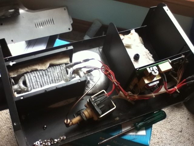 Here is a good overview where we can see the piping that was inside the heat exchanger and the Aluminium that made it up all spread out.
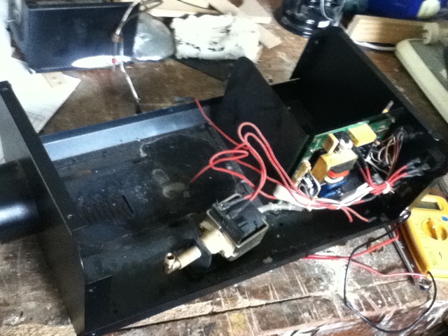 A view with the heat exchanger unit removed from the case.
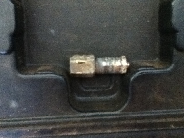 The nozzle(I did mangle it pretty badly when trying to remove it and appear to have shorn through the silver solder(?) that held it onto the end of the smoke pipe.
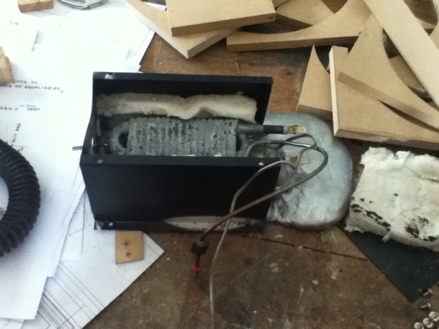 The heat exchanger module. Here you can see the coils of pipe to carry the fog juice, the horizontal heating element and the puddle of solidified aluminium from when it overheated.
So I am going to try and repair it as the only problem seems to be with the heat exchanger(Al structure fully melted and in a puddle in the bottom of the case) and somewhere in either a relay that controls the heating element or the temperature probe. My gut feeling is that the temperature probe is to blame and hopefully I can find a way to test it(perhaps with the oxy-acetylene torch from school). When checked with a multimeter the temperature probe gave a reading of between 0 and 3 ohms at room temp (about 30 degrees C) and a voltage reading of 0V(2000mV scale). If it were a thermistor I would expect the resistance to be somewhat higher and if it were a thermocouple I would expect a higher voltage(from a little reading on Wikipedia).
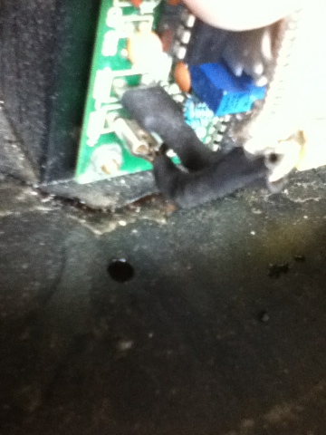
Just a quick picture to remind me which way to connect the temperature probe. It appears to be polarised which makes me think it's a thermocouple. If it is a thermocouple and a wire has broken from repeated heating/cooling cycles then that may explain the lack of voltage and the lack of voltage would explain the amount of heat applied to the heat exchanger when it overheated.
Subscribe to:
Posts (Atom)