
Sunday, 23 December 2012
DSO Block Digram
Wednesday, 19 December 2012
DSO Revelations
So today while doing the thoroughly mentally stimulating task of watering trees at work all day I had an epiphany. I am building a Digital Storage Oscilloscope ie. I can have 2 programs that run and have them mutually exclusive. A capture program that reads the state of the ADC(s) and pushes them to a more stable memory location(seperate section of RAM, Main HDD[my be a section of flash memory on board] or Dedicated section of Flash memory). The pseudo-code for this would be along the lines of:
This would give a sampling rate that can be calculated fairly easily. The instructions are fairly basic so they should each only take 1 cycle to execute. Therefore 5 cycles are required to monitor the state. Therefore we just divide the clockspeed of the CPU by 5 to give us the sampling frequency(assuming CPU at 1GHz):
The other program would be a GUI that allows the "settings" to be adjusted and a graph to be displayed. The "settings" would only effect the display. Unless I decide to implement software controllable attenuation or something useful like that. The attenuation would be done before the ADC and would be instructed to attenuate through the communication bus from the ADC which is activated for reverse transmission by sending a pin to say -5V which shouldn't happen in any other situation.
Anyway is anyone finds this helpful/instructive/wrong don't hesitate to leave a comment, more comments inspires me to write more :)
p.s. If anyone sees the HTML tags wrong or wants me to go through the tags I used here let me know any I'll put something up.
Reset counter

While Stop = False do


 Move state_of_ADC to register0

Move register0 to Permanent_Location[counter]

counter = counter +1

EndWhile
This would give a sampling rate that can be calculated fairly easily. The instructions are fairly basic so they should each only take 1 cycle to execute. Therefore 5 cycles are required to monitor the state. Therefore we just divide the clockspeed of the CPU by 5 to give us the sampling frequency(assuming CPU at 1GHz):
1GHz/5=200MHz
That's a 200MHz sampling rate. The only problem with this method is that the only real way to change the sample rate is to change the CPU's clock speed... But if I'm going to build a radio from scratch then I dare say I'll get used to adjusting frequencies with a voltage...The other program would be a GUI that allows the "settings" to be adjusted and a graph to be displayed. The "settings" would only effect the display. Unless I decide to implement software controllable attenuation or something useful like that. The attenuation would be done before the ADC and would be instructed to attenuate through the communication bus from the ADC which is activated for reverse transmission by sending a pin to say -5V which shouldn't happen in any other situation.
Anyway is anyone finds this helpful/instructive/wrong don't hesitate to leave a comment, more comments inspires me to write more :)
p.s. If anyone sees the HTML tags wrong or wants me to go through the tags I used here let me know any I'll put something up.
Sunday, 9 December 2012
Not a thermocouple? :/
I just wired up a test harness to see what voltage the smoke machine would cut off current to the heating coil when I stopped(pretty unusual) and thought(don't know where this came from...) I should probably test it without anything connected to the PCB just to see what happens. So I did and lo and behold, it thought it was up to temperature... Check the voltage accross the pins... 2.5-3V there... Resistance of the temperature probe? 3 ohms... Hmmm... might not be a thermocouple... time for some more tests...
Attach the probe to PCB... heater turns on... remove it heater turns off... I can hear the relay ticking so that's not what caused it to overheat... some more research needed methinks... Wikipedia here I come...
Attach the probe to PCB... heater turns on... remove it heater turns off... I can hear the relay ticking so that's not what caused it to overheat... some more research needed methinks... Wikipedia here I come...
mV Voltage Divider
Rather than just getting a high resistance to drop the voltage I realized that a higher current would also. By putting a resistor in parallel with the potentiometer I can increase the current flowing through the first resistor and use a smaller, more available resistor there to drop the same voltage.

This is the schematic I did up in KTechLab to test my theory. the 1M resistor represents the smoke machine input. the max. voltage possible with this arrangement is about 30mV(50mV with a 5V supply). This means I should be able to supply the required 25mV for my max. temperature.
Saturday, 8 December 2012
Thermocouple woes
Looking at the Wikipedia page on thermocouples I found this table:
I also had a closer look at the sheaths that the wires for the thermocouple are insulated with. The one going to the +ve port had red lines and the one to the -ve port had what appeared to be black lines in it. The background colour is white.
Based on that table then and if we assume the black is actually a very dark blue then the thermocouple used is most likely going to have been a K type which appear to be fairly popular so it should be easy to find a new one.
With 41 µV/°C I can calculate the maximum voltage I'll need to be able to spoof the thermocouple up to 600°C. I picked this as it shouldn't even go close but in case it does I can still test it.
| Type | Temperature range °C (continuous) | Temperature range °C (short term) | Tolerance class one (°C) | Tolerance class two (°C) | IEC Color code | BS Color code | ANSI Color code |
|---|---|---|---|---|---|---|---|
| K | 0 to +1100 | −180 to +1300 | ±1.5 between −40 °C and 375 °C ±0.004×T between 375 °C and 1000 °C | ±2.5 between −40 °C and 333 °C ±0.0075×T between 333 °C and 1200 °C | |||
| J | 0 to +750 | −180 to +800 | ±1.5 between −40 °C and 375 °C ±0.004×T between 375 °C and 750 °C | ±2.5 between −40 °C and 333 °C ±0.0075×T between 333 °C and 750 °C | |||
| N | 0 to +1100 | −270 to +1300 | ±1.5 between −40 °C and 375 °C ±0.004×T between 375 °C and 1000 °C | ±2.5 between −40 °C and 333 °C ±0.0075×T between 333 °C and 1200 °C | |||
| R | 0 to +1600 | −50 to +1700 | ±1.0 between 0 °C and 1100 °C ±[1 + 0.003×(T − 1100)] between 1100 °C and 1600 °C | ±1.5 between 0 °C and 600 °C ±0.0025×T between 600 °C and 1600 °C | Not defined. | ||
| S | 0 to 1600 | −50 to +1750 | ±1.0 between 0 °C and 1100 °C ±[1 + 0.003×(T − 1100)] between 1100 °C and 1600 °C | ±1.5 between 0 °C and 600 °C ±0.0025×T between 600 °C and 1600 °C | Not defined. | ||
| B | +200 to +1700 | 0 to +1820 | Not Available | ±0.0025×T between 600 °C and 1700 °C | No standard use copper wire | No standard use copper wire | Not defined. |
| T | −185 to +300 | −250 to +400 | ±0.5 between −40 °C and 125 °C ±0.004×T between 125 °C and 350 °C | ±1.0 between −40 °C and 133 °C ±0.0075×T between 133 °C and 350 °C | |||
| E | 0 to +800 | −40 to +900 | ±1.5 between −40 °C and 375 °C ±0.004×T between 375 °C and 800 °C | ±2.5 between −40 °C and 333 °C ±0.0075×T between 333 °C and 900 °C | |||
| Chromel/AuFe | −272 to +300 | n/a | Reproducibility 0.2% of the voltage; each sensor needs individual calibration. | ||||
Based on that table then and if we assume the black is actually a very dark blue then the thermocouple used is most likely going to have been a K type which appear to be fairly popular so it should be easy to find a new one.
With 41 µV/°C I can calculate the maximum voltage I'll need to be able to spoof the thermocouple up to 600°C. I picked this as it shouldn't even go close but in case it does I can still test it.
With 3.3V avaliable from an old ATX PSU and (with some help from here) a voltage of 25.703mV(measuring 600°C reference 20°C) accross the thermocouple:
Voltage drop across fog machine=0.025703V
Voltage drop across resistors=3.274297V
Current flow from fog machine=V/R
=0.025703/1000 000
=0.000000026A
Resistance required=V/I
=3.274297/0.000000026
=125934500Ω
=125934.500kΩ
=125.934500MΩ
Which is pretty close to 126MΩ
However when I run this through KTechLab (Better than a SPICE simulator for a quick calculation) 10MΩ seems to be enough... perhaps I neglected to calculate current flow through the resistance array? I'll re-post once I have more info...
Sunday, 2 December 2012
More progress on the fog machine
To test my hypothesis about the temperature sensor being a thermocouple I realized that a thermocouple would have something like an op-amp as a buffer amp and to get the low voltage up to a logic level. An op-amp has an (ideally) infinite (actually) really high input impedance. This high impedance means that the amp does not load down the input circuit with high current draw.
I=V/R
I=V/infinity
I=0
This is why an op-amp has a high input impedance.
The temperature probe connections have a resistance of around 1000k. That's pretty high, which when coupled with the polarity markings indicates that there is an op-amp on the board and the temperature probe is a low current voltage source. Also known as a thermocouple.
This means I can now simulate the presence of the temperature probe by supplying an appropriate voltage(not sure how big yet though). By simulating the presence of the thermocouple I can test if the electronics will turn off the heater current at some point which means that it was just the thermocouple that failed. The outer braid of the thermocouple has failed where it enters the remains of the aluminium so that makes me think that something went badly wrong with the thermocouple.
While I had the multimeter out I also measured the heater coil's resistance- this came out at about 700k. So with a little math we can calculate the current flowing through the coil and also the wattage(not really that important but might be interesting to see how much power the electronics use).
I=V/R
I=230/700k (Pretty sure 230V isn't RMS but I know it isn't Peak to Peak so it shouldn't give us a number that is too high)
I=230/700 000 (Now in SI units)
I=0.003288571A (Seems very very low ???)
Now for power consumption:
P=IV
P=230*0.003288571
P=0.76W
This is clearly wrong so I decided to check again... It turns out that my fingers have a resistance of around 700k ohms and it was this resistance I measured. The heating coil appears as an open circuit so I think I'm going to have to melt out the remains of the Aluminium block and get a closer look.
I=V/R
I=V/infinity
I=0
This is why an op-amp has a high input impedance.
The temperature probe connections have a resistance of around 1000k. That's pretty high, which when coupled with the polarity markings indicates that there is an op-amp on the board and the temperature probe is a low current voltage source. Also known as a thermocouple.
This means I can now simulate the presence of the temperature probe by supplying an appropriate voltage(not sure how big yet though). By simulating the presence of the thermocouple I can test if the electronics will turn off the heater current at some point which means that it was just the thermocouple that failed. The outer braid of the thermocouple has failed where it enters the remains of the aluminium so that makes me think that something went badly wrong with the thermocouple.
While I had the multimeter out I also measured the heater coil's resistance- this came out at about 700k. So with a little math we can calculate the current flowing through the coil and also the wattage(not really that important but might be interesting to see how much power the electronics use).
I=V/R
I=230/700k (Pretty sure 230V isn't RMS but I know it isn't Peak to Peak so it shouldn't give us a number that is too high)
I=230/700 000 (Now in SI units)
I=0.003288571A (Seems very very low ???)
Now for power consumption:
P=IV
P=230*0.003288571
P=0.76W
This is clearly wrong so I decided to check again... It turns out that my fingers have a resistance of around 700k ohms and it was this resistance I measured. The heating coil appears as an open circuit so I think I'm going to have to melt out the remains of the Aluminium block and get a closer look.
Saturday, 1 December 2012
FM-1500 Fog machine heat exchanger melted
Today I was given the smoke machine that we tried to use at a gig a few months ago where it tried to burn down the hall. Thankfully it only burnt a hole in the floor a bit.
So I am going to try and repair it as the only problem seems to be with the heat exchanger(Al structure fully melted and in a puddle in the bottom of the case) and somewhere in either a relay that controls the heating element or the temperature probe. My gut feeling is that the temperature probe is to blame and hopefully I can find a way to test it(perhaps with the oxy-acetylene torch from school). When checked with a multimeter the temperature probe gave a reading of between 0 and 3 ohms at room temp (about 30 degrees C) and a voltage reading of 0V(2000mV scale). If it were a thermistor I would expect the resistance to be somewhat higher and if it were a thermocouple I would expect a higher voltage(from a little reading on Wikipedia).
 Here is a good overview where we can see the piping that was inside the heat exchanger and the Aluminium that made it up all spread out.
 A view with the heat exchanger unit removed from the case.
 The nozzle(I did mangle it pretty badly when trying to remove it and appear to have shorn through the silver solder(?) that held it onto the end of the smoke pipe.
 The heat exchanger module. Here you can see the coils of pipe to carry the fog juice, the horizontal heating element and the puddle of solidified aluminium from when it overheated.

So I am going to try and repair it as the only problem seems to be with the heat exchanger(Al structure fully melted and in a puddle in the bottom of the case) and somewhere in either a relay that controls the heating element or the temperature probe. My gut feeling is that the temperature probe is to blame and hopefully I can find a way to test it(perhaps with the oxy-acetylene torch from school). When checked with a multimeter the temperature probe gave a reading of between 0 and 3 ohms at room temp (about 30 degrees C) and a voltage reading of 0V(2000mV scale). If it were a thermistor I would expect the resistance to be somewhat higher and if it were a thermocouple I would expect a higher voltage(from a little reading on Wikipedia).
Just a quick picture to remind me which way to connect the temperature probe. It appears to be polarised which makes me think it's a thermocouple. If it is a thermocouple and a wire has broken from repeated heating/cooling cycles then that may explain the lack of voltage and the lack of voltage would explain the amount of heat applied to the heat exchanger when it overheated.
Thursday, 29 November 2012
Laptop Oscilloscope original state
Here are the photos as promised yesterday. I apologise for the quality but my iPod 4G was pretty much the only camera that functions reasonably well and reliably.

 The basic overview. The tag in the back right corner is a repair tag from when grandpa got it fixed at some stage.

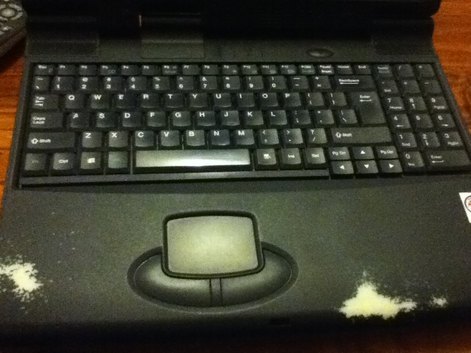
 A view of the screen, keyboard and mousepad. the screen and keyboard should be re-usable but I'll need to find a new mousepad and buttons.


 Here is the backplate with (L to R) VGA out, RS-232, 2xUSB, proprietry breakout plug, RCA video out, S-Video out, Printer port.
 2.5" HDD bay.
 CDROM sitting on top of HDD bay to get some angle on the front.
 Zip and Floppy drives side by side on top of HDD on top of CDROM, once again for some angle.
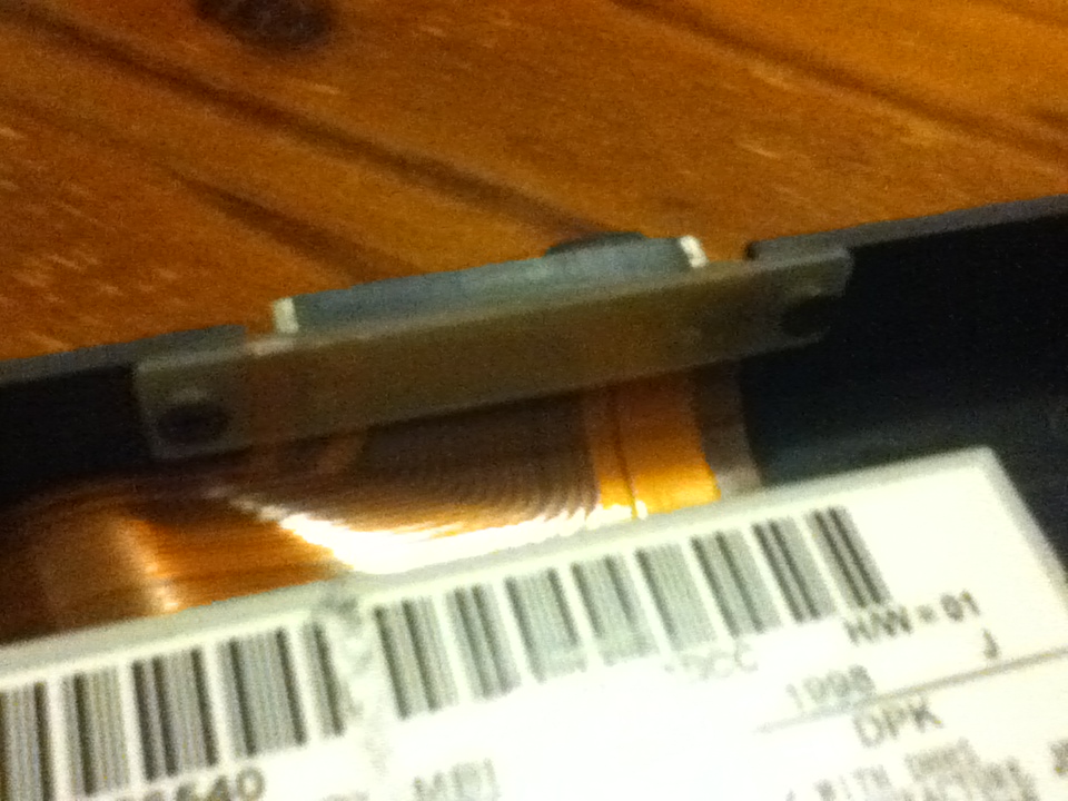
 A close up of the connector. Should be pretty easy for me to put in my own connectors.
 The where the battery was. It's a pretty big hole and a raspberry pi would probably fit in this space alone. Maybe some other pluggable module... Perhaps a replaceable CPU/RAM module or something.
 The battery in all it's brick-like glory. It doesn't work as a battery anymore but if I did want to I could probably re-pack the original cells... Perhaps even increasing the capacity. :)
If you want any more detailed pictures or info post a comment and I'll get some for you.


Some views of the bottom. At bottom with all of the removable sections partly removed. Clockwise from top right there is the CDROM drive, HDD bay, Floppy/Zip drive bay.

Here all of the removable modules are removed. Bottom left we can see the modem module with broken ribbon cable from a previous teardown I did.


If you want any more detailed pictures or info post a comment and I'll get some for you.
Wednesday, 28 November 2012
Nerf Stampeed electronics upgrade
This is a post I was going to make a little while ago about a fairly basic project to get me into Amtel's AVR microcontrollers... I had some problems with the internet on that day and have only just rediscoverd the draft that was saved :)
So I'm not happy with the stock electronics for the Nerf Stampeed. Using a 7 shot clip you can easily fire away all of your darts and still not hit anything. Also the 6 D cell batteries are a pain to replace and are massively heavy.
So I'm not happy with the stock electronics for the Nerf Stampeed. Using a 7 shot clip you can easily fire away all of your darts and still not hit anything. Also the 6 D cell batteries are a pain to replace and are massively heavy.
The solution:
Put a small microcontroller such as an Amtel AtTiny of some description, replace the current power switch with a 3-way switch to allow selecting between:
-Full Auto(Stock Setting)
-Burst(fires 2 or 3 darts at a time)
-Semi-Auto(fires 1 shot but automatically re-cocks)
Some way of displaying the number of rounds fired in battle and the battery level should be easy to set up. If I can find a way to differentiate between different magazines then a readout showing how many are left in the mag. would also be useful.
A display like this only needs an SPI interface, everything else can be controlled with digital I/O except for reading the battery state, the best solution for which I don't quite know right now but will probably need an ADC channel.
 This is a fairly quick flowchart I did up showing the basic functions that will be called and when... not quite up to drawing a flowchart to show exactly how each function works... but I figure this is a start.
If you want to know why I did up a flowchart for this just ask me to put up the Qt code and flowchart that I taught myself and wrote in 1 week or so... the flowchart was about 2.5m high when printed so small it was barely readable... Originally I was trying to work it all out in my head... doesn't work that way... not like the simple little things they wanted me to do flowcharts for in my sfotware design and development course...

If you want to know why I did up a flowchart for this just ask me to put up the Qt code and flowchart that I taught myself and wrote in 1 week or so... the flowchart was about 2.5m high when printed so small it was barely readable... Originally I was trying to work it all out in my head... doesn't work that way... not like the simple little things they wanted me to do flowcharts for in my sfotware design and development course...
Finally... New project :)
Finally I've decided what to make my next new project. A DSO... This oscilloscope will be housed in the case of an old laptop that was given to me a while ago by my grandfather after they got a much better one. From memory it's current specs are in the vicinity of: 400-500 MHz processor(Pentium?), 64MB RAM, 4GB 2.5" IDE HDD, broken mousepad, decent screen (will run up to 1024x786?), came with win98, struggles to run cron, X11 and a window manager(twm?) on top of a CLI Ubuntu install.
All this will be replaced allowing me to start from scratch... I will probably keep the keyboard and screen, even if I have to set up an AtTiny or similar to get the interfaces in a format I want. At this stage looking at using an ARM processor or SoC. The CDROM bay will be replaced with pluggable modules with a digital interface to the main board allowing me to change and upgrade input channels or make a computer controlled function generator/DSO that can be controlled from any computer (Running Linux of course :) ). At this stage to allow remote control ethernet/WIFI is planned with an interface probably built from Qt. As well as being remote controllable the oscilloscope will be locally controllable, with the bootloading being handled by coreboot with a linux kernel payload.
I want to be able to use this to help me debug amateur radio rigs up to the 40m band to start with. The pluggable ADC modules allow me to improve if I need better frequency/accuracy. Basic features will include:
-Local control to allow full functionality as a normal DSO.
-Updatable firmware so new features can be implemented.
-Miniumum 50MHz bandwidth for initial product(excluding prototypes).
-Network connectivity to allow remote monitoring.
-Possibly battery, to allow monitoring in locations with limited power outlets
-Using only free and open source tools to design and sharing the designs as open source(github?)
Hopefully soon I'll get a picture of the laptop in it's current condition so you can get an idea of how much space internally I have to work with :)
Wednesday, 31 October 2012
AVRs on the lighting desk
I've been looking at Amtel's AVR microprocessor chips and they look like the next step for my search for a simple cheap lighting desk...
According to this wikipedia page the smallest amount of RAM that an ATtiny has is 32 bytes... now I have 15 8bit fader channels and 12 boolean channels... by my maths that makes 132 Bits... According to the Wikipedia entry on bytes it says that 1 byte ~ 8 bits on most systems... using that conversion I need 16.5 bytes of RAM for my variables, having about half of the RAM in the system means I don't have to worry too much about having to make my code too compact even on the smallest of microcontrollers... I hope...
As to the problem of needing more ADC channels then are provided I can use the I2C bus or 2 wire bus to attach extra ADC chips to the AVR.
That's all for now... exams are almost over and I have a job coming up shortly that should give me some money to spend on this stuff so I can finally get this desk working properly...
Cheers,
Rex
Tuesday, 23 October 2012
New Motherboard
Yesterday after my exam I picked up an old motherboard that the IT guy said he was going to give to me. I'm not exactly sure what it is but it has 8 DDR(1/2?) slots and as far as I can tell 4GB in it so far. It also appears to have 2 PCI-X slots and 3(I think) normal PCI slots.
The really exciting thing about it is that it has 2 separate CPU's!! So naturally when I got it home my brother asked if I was setting it up for gaming... not yet...
I'll try and get some good pics and upload them sometime soonish too...
I plugged it in today and discovered that my PSU's are all really really old... as I only have the 20 pin connectors... but I do have a few of them so I'm going to see if I can hack a few together and get them to drive the board... The biggest problem at the moment is there is another socket next to the main 24 pin ATX power plug, this means (according to wikipedia) that I need an EPS type power supply. on the Wikipedia page for PSU's there is a reference to a .PDF calling itself the EPS design guide so hopefully that will help me hack together something that will work...
Monday, 20 August 2012
MDP Done
Pending testing at school in a few hours my project is done, just needs some error trapping to be implemented though...
EDIT: It does actually work now, the response time is rubbish like I thought it would be, and it seems to drop events occasionally on the PIII that I have the system running on... Might(Maybe) try running it on a Celeron(2.4GHz I think) if I get a chance, just to get it running a bit faster...
EDIT: It does actually work now, the response time is rubbish like I thought it would be, and it seems to drop events occasionally on the PIII that I have the system running on... Might(Maybe) try running it on a Celeron(2.4GHz I think) if I get a chance, just to get it running a bit faster...
Sunday, 19 August 2012
DT MDP

Subscribe to:
Posts (Atom)