I've finally got more work done on the Mill. I was hoping to get a shot of the control box powered up with the laptop running the control software next to it for the cover photo. However it seems that I need to keep playing with the software a little longer.
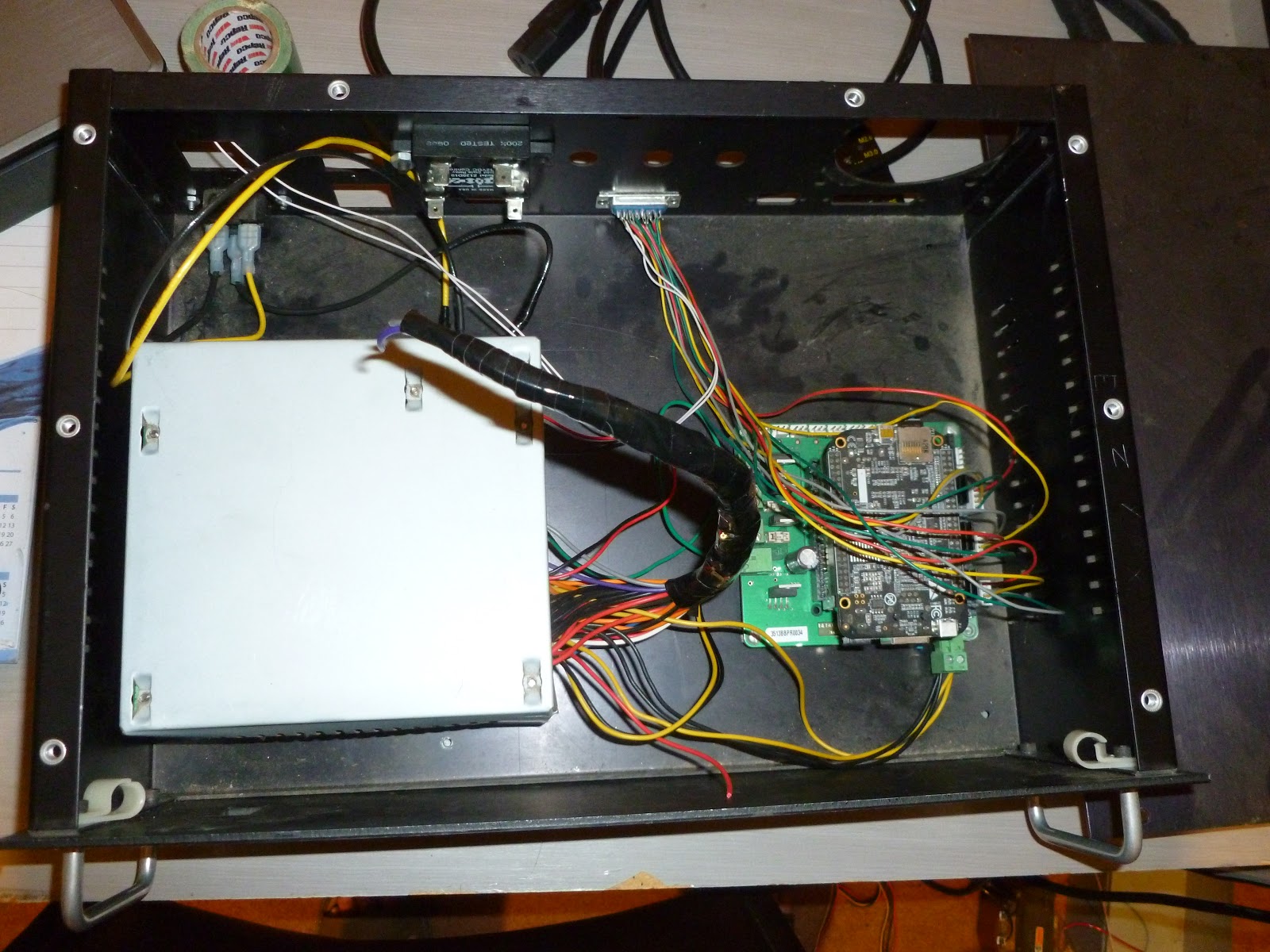
Instead you get a photo of the finished product as it stands. I know the wiring isn't the neatest or prettiest. But you can take my word for it that it does work now. Follow on after the break to see how I got to this point.
I was cleaning up the other day and I discovered an old ATX computer power supply that I was confident still worked. The only issue was that the IEC connector for the power cord in the back was mangled so there was no testing without opening it up and hooking some wires up.
 |
| The specs from the computer power supply I am using. that +12V rail should have enough oomph. |
Thankfully the original case for the control box had an IEC connector in the back of it and the connector for 110V and 240V is the same. This means that all I need to do is get some wires to connect it to the power in on the circuit board for the re-purposed power supply.
 |
| The inside of the IEC connector. |
The connector even had spades on it so all I needed to do was splice in some wires from the original wiring harness onto the ends of the wires that I cut free from the bad IEC connector on the new power supply.
To get these spade connectors that I needed to splice in I found in my electronics box a cable with 2 mains wires heat shrinked inside and another loose wire for the earth.
 |
| The pit of dispair. |
 |
| This is what the cable looked like before I started with it. |
I cut back the heatshrink from the outside and discovered that the earth wire that leads out of the bundle is actually connected to a shield. There seems to be a lot of them in the multicore bundles on this machine. I wonder if they were worried about noise?
I quickly pulled the power suppy apart to get a quick look and inspection to make sure everything is as it should be, which it is.
To mount it I just put a few more holes in the bottom of the case and used the existing holes that are threaded into the top of the supply to mount it upside down in the case. This gives me a good solid mounting and also means that it's a little safer if I any of the capacitors on the supply remain charged after removing the power. With the grounded metal case facing up like that you'd have to reach under it to touch high voltage live wires.
At this point it was just a case of splicing in the new mains power connector and cutting away any unneeded wires, then hooking them up to the control circuit board.
 |
| Chop it! |
 |
| These 2 plugs are wired up to the +12V rail and GND. They plug straight into the control board. |
Once this was done all that was left was to wrap up all of the unneeded wires neatly so if I do need a +5V rail at some point I can get it easily.
From here I put the lid on and tested it. Everything worked as advertised. Now all that's left to make work is the spindle needs power and possibly a speed readout depending on how fancy I feel and a little fiddling with the software stuff to make it actually controllable.
Until next time
Cheers,
Rex


No comments:
Post a Comment